/

Product

TechnoboxProductsPCI Mezzanine Cards (PMC)I/O16-Port RS485/RS422 Asynchronous Serial Communications Adapter PMC

16-Port RS485/RS422 Asynchronous Serial Communications Adapter PMC

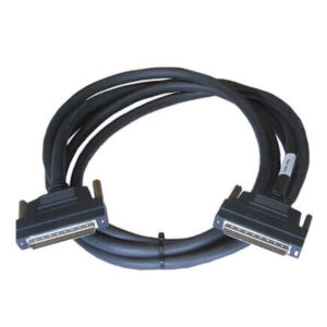
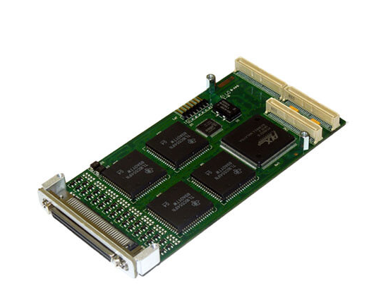
Our 16-Port RS485/RS422 Asynchronous Serial Communications Adapter PMC (5463) provides sixteen 16550-based UARTs using RS422 or RS485 signaling levels. All sixteen ports are available out the PMC front-panel via a 68-pin SCSI-style connector.

RoHS Compliant

Lead-Free

Industrial Temperature

Datasheet

Get a Quote

Order Now

SKU: 5463 Categories: ,

Product Information

The Technobox, Inc. P/N 5463 16-Port Async Communication adapter provides sixteen 16550-based UARTs using RS422 or RS485 signaling levels. Each port provides two differential pairs of RS485 data: TX/RXA+ (Transmit/Receive A Data +), TX/RXA (Transmit/Receive A Data -), TX/RXB+ (Transmit/Receive B Data +), TX/RXB- (Transmit/Receive B Data -). A Programmable Logic Device (PLD) located between each UART and the RS485 device permits a variety of interface operation. RS422 IN/OUT, RTS/DTR controlled RS485 bidirectionality, or a combination of these are possible for each MAX487E circuit. The TXD output from the UART can drive both differential pairs, and the RXD input to the UART can be sourced from either differential pair.

All sixteen ports are available out the PMC front-panel via a 68-pin SCSI-style connector. Also, the ports are wired to the P4 connector at the rear of the PMC, allowing connection of all sixteen ports to the VMEbus P2 connector for host processors supporting rear-I/O connection. An optional transition panel converts the 68-pin SCSI style connector into sixteen RJ-11 connectors. The 6-pin RJ-11 connector provides a convenient, inexpensive, and space-efficient means to connect the ports to standard 9-pin or 25-pin D-Sub connectors at the user’s equipment using readily available RJ-11 modular jack to D-sub adapters. For Rear I/O, a paddle card (purchased separately) converts the P2 ‘a’ and ‘c’ rows back into the 68-pin SCSI style connector. This permits use of the sixteen connector RJ-11 transition panel for rear-exit from the card cage.

The UARTs operate at standard baud rates from 300 baud to 115K-baud. Other higher and non-standard baud rates are possible and are available on special order. The interrupt control logic allows reading the state of the interrupt requests from all 16 UARTs in a single access. This logic also provides a priority-encoded value for even faster interrupt processing. The interrupts are presented on one of the PCI INTx lines (x = A, B, C, D). The default connection of INTA may be changed by PLD reprogramming.

The Interface used in this design is a MAX487E (or equivalent). This provides slew-rate limited transitions (up to 250 Kbaud allowed) and 10KV ESD discharge tolerance. Also, each RS485 pair is provided with discrete clamping diodes together with Transient Voltage Suppressers (TVS). This practice further enhances the interface to surge and noise voltages. 120 Ohm termination is provided for RS485 differential pair. The user may selectively remove the termination resistor for each port. Other termination values are available on special build. The 16550-register set is accessed from the host processor using Programmed-I/O. “C” source code is provided with the board to illustrate how to set up the PCI bus bridge in order to access the UART registers.